Testing
The second part of getting up to better production standards is testing. While I've always done testing, it's usually a slow process of fiddling with sockets and checking each point with a multimeter by hand.
For v2.0 of the Breadboard PSU an important design decision was to include better support for being able to test the assembled boards quickly. The intention was to take advantage of one of these.. a pogopin:
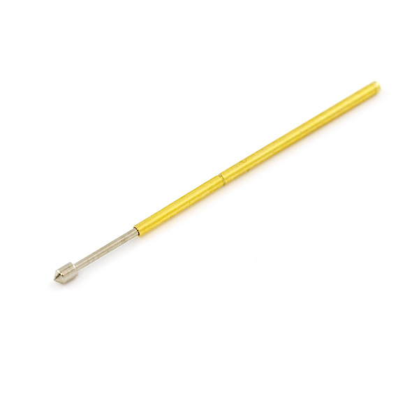
Pogo pins are a spring-loaded conductive pin which can be soldered in like a header pin. They are small enough to fit standard holes boards already usually have for various kinds of headers, and come in a variety of tips, including ones which make solid contact with flat exposed pads.
The output sides of the board already have useful holes to connect a pin to, but the input side didn't have anything. So v2.0 has two holes down by where the DC jack is soldered specifically for pogopins during testing.
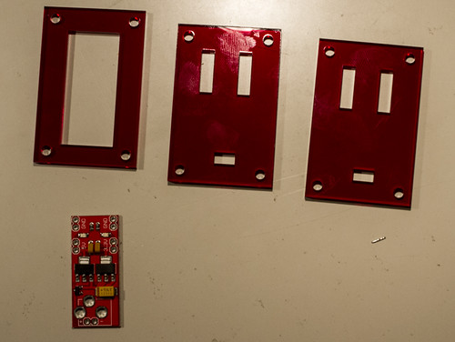
The next part is making the testing frame. For this, I used the laser cutting services of Ponoko. These are the plastic cuts I designed and had cut:
 '
'
The three pieces make up a bottom layer to hold a sacrificial PCB, and two top layers, one of which is just used to assist on placing the board. The small holes are to allow the pogopins to pass through, with bolt holes in each corner.
The sacrificial board is one of the boards from the panel with nothing soldered down to it. Pogo pins are soldered down on the existing holes, and additional wires are soldered to pads and holes which connect to the same signals.
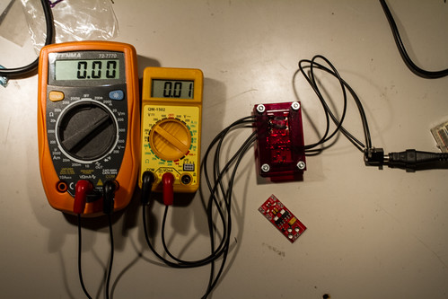
The whole contraption, connected to a pair of multimeters and a DC jack, looks a bit like this:
From the side, you can see the way the pins are arranged to allow contact from a board under test:
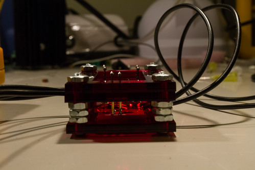
This is probably not ideal, the pins are too high, but you get the general idea.
All that needs to be done now to test a board is press it down on the array of pins, and check the meters and LEDs are lit:
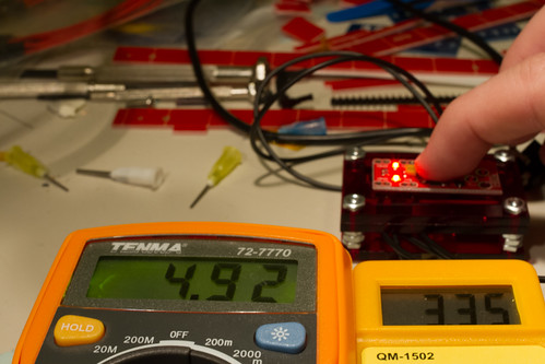
As you can see, the LEDs are lit confirming that they've been soldered down correctly (for once!), and the voltages of both sides of the output. This board was rejected after testing, as the 5V output is too low.
Testing is a critical part of making sure the products you make are working as the end user expects. By using a testing jig like this, I can test a board in about 5 seconds.
Using a small MCU, a more complete testing platform could be made, that automatically measures voltages, or flashes firmware images, or interrogates the target board to ensure it operates normally.
All you need is a bed of pogopins, and some imagination.