0R and you
Recently on Twitter I made a comment about my supplies of zero ohm resistors (0R) going missing, and I was asked why it mattered since they're just a wire link.
It's true that effectively a 0R is a wire link in intent, but that's not necessarily the best way to think of them, and in many cases you actually want something which doesn't look like a wire link at all.
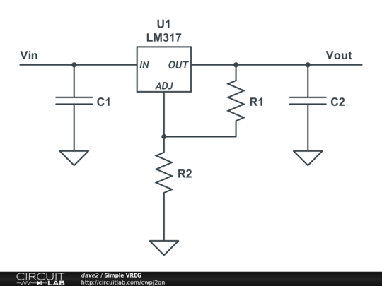
Let's say we have designed a small linear voltage regulator into a board. The most flexible design is one using an adjustable regulator, since we can set it to any desired output voltage. The circuit for that is below:
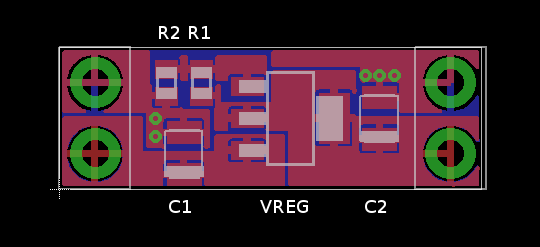
An adjustable regulator has the output voltage set by changing R1 and R2. Laying this out on a PCB, we end up with something like:
We're using SMD components for this board. C1 and C2 are either side of the regulator in the middle. R1 and R2 are above C1 and control what voltage we want.
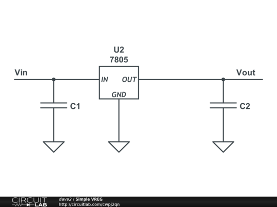
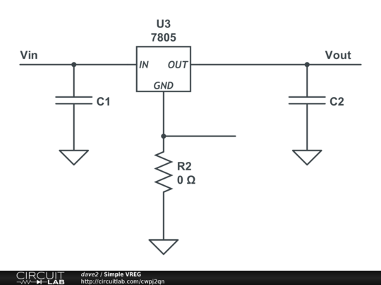
Most voltage regulators also come in a fixed version: R1 and R2 are hidden inside the regulator, so we don't need to place them outside on the board like this is laid out. Instead, that adjust pin has to be tied to ground like this:
That ADJ pin is now a GND pin. If we look at our PCB, we can see we don't need to populate R1 any more (there is no connection from Vout to the pin via a resistor), but what about R2. It was a resistor, now it has to be a link. We could design a new board, but if we look at how R2 just needs to become a link, we can do this instead:
This is where we'd use a 0R, they are not just a wire link but the same package as any other resistor. They are physically built the same as any other resistor we could use there, so we don't need to design a whole new board.
This means we can use both fixed and adjustable versions depending on what we have available, on the same board design, with the same size components. Designing a board for implementation flexibility (in this case, being able to use both types of regulator) improves what they are capable of, so you'll often find 0Rs on many boards.


