RGB Clock
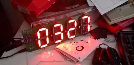
I wanted a large-digit NTP sychronised clock that handled daylight saving and automatically adjusted brightness for ambient light, so I never need set it or have to deal with bright clocks in dark rooms, or unreadable clocks in bright rooms. There are lots of these around, and here’s mine!
Note: I’ll update this page with the source files when I get around to it! It’s all under CC: BY-SA anyway.

Hardware
To allow this clock to have any colour and adjustable brightness, I chose cheap serial-driven chainable RGB LEDs that include a driver inside each LED. The whole display is treated as a single string of LEDs, arranged in the familar 7-segment format. It only requires one IO pin to control all 28 segments of a 4-digit display.
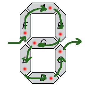
Each digit is wired in a specific order to make it easier to route. Rather than following conventional ordering, the LEDs form a loop which doesn’t cross over itself at any point like this:

This makes it easy to design a board and simple to drive with off-the-shelf code. The LEDs I used are WS2812B clones in a standard 5mm diameter LED package, with a through-hole mount. The clones I used are labelled as APA106, and have slightly different timing requirements to WS2812B. (This involved some hacking on the C side of the MicroPython NeoPixel library to adjust the timings it generated.) There are a heap of such clones on Aliexpress and other similar sites.
The shell is 3D printed in black ABS plastic, based on an OpenSCAD project for parametric LED segment displays. You can find the source I used for this here:
Customizable Large 7 Segment Display with Std LEDs
Each segment has a hole for an LED, and a shaped well. After the LEDs are positioned each well is filled with hot glue as a simple diffuser. It works well enough to fill each segment with colour to an acceptable enough level. There are better ways to do LED diffusion but this is a cheap method that works well with the 3D printed shell.
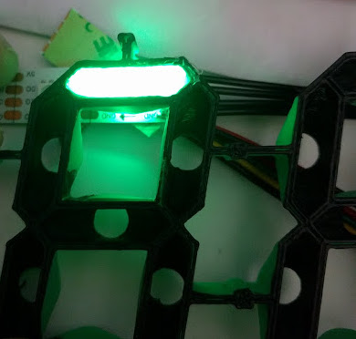
Here’s an early test of LED diffusion using hot glue in the 3D printed shell. You can see the holes in the shell where the LEDs are inserted.

The controller I used was an ESP8266-based breakout. The board includes an LDR wired to the single analog input put on the ESP8266. There is also a 74HCT125 acting as a level shfiter. Although this is a bit overkill for a single IO pin, I had heaps of them around and they’re very cheap.
Power is a straight 5V DC input, provided up to the ESP8266 board as well rather than drawing the LED power from the USB port on the ESP8266 board. This allows a high current draw and less concerns about what is being drawn over USB. The ESP8266 board I used had a diode and fuse between VBUS at the 5V pin, which in turn meant the 5V pin wasn’t quite 5V when powered by USB. The diode was removed to isolate USB VBUS from the 5V being provided on the DC jack.
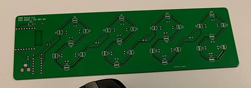
All the LEDs, ESP8266 breakout, some caps for stability on the 5V rail, and the 74HCT125 are soldered to a single PCB for the whole display. This simplified the build at the cost of a slightly more expensive PCB. The board was quickly knocked out in KICAD, and checked against the 3D printed shell before sending off to be made.

Software
The ESP2866 board is running MicroPython, making it easy to debug and code for. Although in the past I wrote everything for MCUs in C, I decided to use MicroPython this time to speed up the development. Plus, given these were serial driven LEDs, there wasn’t a lot of need for fast timing outside the serial LED code that MicroPython already had.
Although the LEDs are RGB, it’s actually easier for us to work in HSV when dealing with strips. This allows us to pick colours more directly using the H (hue) value, and adjust the overall brightness with the V (brightness) attribute. We keep S (saturation) at 1, which gives us a solid colour. If S was 0, then the result is white regardless of the value for H.
The NeoPixel library needs RGB values (although our pixels are in GRB order, so we have to send in that order) between 0 and 255 for each channel. The HSV is expressed as a float, so we need to both convert from HSV to RGB but also scale to the expected RGB channel range.
(Yet to be implemented is per-LED-channel characterisation to give every segment an equal apperance, and to balance different channel brightness for the same input, but this can be easily added during the HSV to RGB conversion. Also changing the brightness based on LDR input is still outstanding. But this is also very easily added, since we can just set V based ADC values scaled to a 0..1 range.)
There is a lookup table of digits to segment on/off (expressed using True and False). This way we can easily choose a colour per-segment if we want. Each digit is written out into the NeoPixel’s LED buffer, with either a colour or all-off for False values in the lookup table.
The time source used is the ESP8266 RTC, itself synchronised from an NTP server. This is resynced every hour or so as it’s not clear how much drift there is in the ESP8266 RTC, and it doesn’t hurt much to poll for NTP that often.
There are probably a bunch of better ways to do this, but it’s just a quick hack!