AVR Programmer Usage
Target Connections
Programming a target with the hairy.geek.nz AVR programmer is no different to using any other ISPmkII clone, however to save space the connector is expected to be used with a "squid" cable or single pin connectors.
In all connections, "GND" should be connected to the target's ground, and "VCC" to the target's VCC. The target must be powered up, and supply current to the VCC pin.
ISP Mode (SPI)
ISP Mode is used on mostly MEGA series microcontrollers. In ISP mode, the target AVR is programmed using its SPI port and !RESET line. The pin-out for this mode of the programmer is as follows:
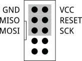 Connect each of these pins to their respective target pins (ie, MISO goes to MISO on the target). Also ensure GND and VCC are connected to their respective lines on the target.
TPI Mode
TPI Mode is mostly used on the AT Tiny series of low pin-count microcontrollers, and uses two pins repurposed in programming mode for bi-directional data and clocking, along with the !RESET pin. The pin-out for this mode of the programmer is:
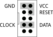 Connect the CLOCK pin to TPICLOCK, DATA to TPIDATA, and RESET to !RESET. Also ensure GND and VCC are connected to the respective lines on the target.
PDI Mode
PDI Mode is used by the XMEGA series of microcontrollers, and provides both programming and debug support. Only programming is supported by this board. PDI Mode uses a single dedicated bi-directional data pin, with !RESET doubling as both clock and how the chip is forced into programming mode. The pin-out for this mode of the programmer is:
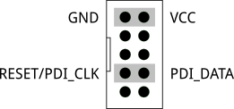 Connect Reset/PDI_CLK to !RESET/PDI_CLK, and PDI_DATA to PDI_DATA. Also ensure that the GND and VCC pins are connected to their respective pins on the target.
Rescue Clock
A common problem with programming Tiny and MEGA chips is the need to set fuses to specify an external clock, and if this clock fails you have no way to program the chip to use its internal clock instead. To assist with recovering chips in this state, the programmer provides a 4MHz rescue clock on one of the pins:
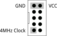 This clock can be used in any of the modes, it is always available.
Updating the firmware
Updating the programmer's firmware can be done without requiring any special hardware.
- Disconnect the programmer from the USB port
- Hold down the button while reconnecting the programmer to the USB port
- Board is now in DFU programming mode, and will accept a new firmware upload
- Once flashing is complete, disconnect the USB port, and reconnect it without holding down the button.
Replacing the bootloader
Should the bootloader on the programmer need to be replaced, you will need an external AVR ISP programmer in SPI mode.
Solder a jumper to JP1 and close it. This will provide power from the programmer side of the board to the target side. Do not leave this jumper closed for normal operation, only connect for bootloader updates.
Now use the following connections on the target connector. These are from the perspective of another programmer - that is these are the board-as-target:
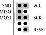 Note that !RESET is in a different position to where it is ISP mode when being used as a programmer. Connect the pins as labelled to the external programmer.
Ensure JP1 is open at all other times, otherwise you may damage target boards or this programmer.